0 引言
为缓解经济发展和能源供需区域不平衡,实现大规模“西电东送”和“北电南送”,我国需要加快特高压输电工程建设。近几年特高压直流输电在国内受到高度重视,成为输电领域的研究热点[1-3]。
换流站阀厅是特高压直流输电系统的枢纽,是实现交流系统和直流系统能量传递的场所,其主要设备包括:换流阀、避雷器、管母、直流穿墙套管、变压器出线套管、各种类型的均压环等,它们有些采用悬吊式安装,有些通过支柱绝缘子支撑,设备与设备之间呈空间布置,相互连接比较复杂[4-5]。换流站阀厅内高压端金具对地电位很高,故在设计阶段应对金具表面电场进行分析,以确定各个金具的形状和尺寸,使场强维持在合理的水平,以确保金具无电晕产生,保证阀厅设备可靠运行[6]。
目前,国内外对特高压直流换流站阀厅内部电场仿真已做了部分研究,文献[7]基于有限元法和瞬时电位加载法计算了±800 kV特高压直流换流站阀厅各金具表面电场分布,但不能同时兼顾计算代价和计算精确度;文献[8]提出了3维自适应有限元并行计算方法,实现了对660 kV阀厅电场的数值模拟,使求解时间大大缩短;文献[9]提出了一种基于模块化与独立化的剖分思想,解决了复杂模型网格剖分困难问题。上述研究都基于有限元法,计算时需要剖分整个区域,自由度较多,对计算机要求高,计算代价大。电磁场数值计算的另外一种典型方法是边界元法,该方法只需离散模型的表面,降低了求解问题的维度,自由度较少,对处理复杂模型有一定的优势,且精度较高。文献[10-11]应用边界元法对换流阀屏蔽罩表面电场进行了计算,但并没有求解整个阀厅内部金具表面电场。
本文针对某±800 kV特高压换流站阀厅金具,采用Pro/E建立了典型金具的3维几何模型,并导入ANSYS进行剖分处理,最后通过伽辽金边界元法进行数值计算,获得换流站阀厅典型金具的电场分布,该计算结果对阀厅金具设计具有重要的指导意义。
1 边界元计算原理
由于区域内任意一点的电位由区域内的所有电荷共同产生,因此场点
\(\varphi (r)=\iint_{{{S}'}}{\frac{\sigma ({r}')}{4\mathrm{ }\!\!\pi\!\!\text{ }{{\varepsilon }_{0}}R}}\mathrm{d}{S}'\) (1)
式中:
利用伽辽金加权余量法对式(1)进行离散,则式(1)可转化为
\(\begin{align}4\mathrm{ }\!\!\pi\!\!\text{ }\sum\limits_{e}{\sum\limits_{j}{\sum\limits_{i}{\iint\limits_{{{S}_{\mathrm{e}}}}{{{N}_{j}}{{N}_{i}}{{\varphi }_{i}}\mathrm{d}S=}}}} \\\sum\limits_{e}{\sum\limits_{{{e}'}}{\sum\limits_{j}{\sum\limits_{i}{\iint\limits_{{{S}_{\mathrm{e}}}}{{{N}_{j}}}}}}}\iint\limits_{{{S}_{\mathrm{e}}}^{\prime }}{\frac{{{N}_{i}}}{R}}\frac{{{\sigma }_{i}}}{{{\varepsilon }_{0}}}\mathrm{d}{S}'\mathrm{d}S \\\end{align}\) (2)
式中:
\(U={{[{{\varphi }_{1}},{{\varphi }_{2}}\cdots ,{{\varphi }_{n}}]}^{\mathrm{T}}}\) (3)
\(E={{[{{\sigma }_{1}},{{\sigma }_{2}}\cdots ,{{\sigma }_{n}}]}^{\mathrm{T}}}/{{\varepsilon }_{0}}\) (4)
由式(5)、(6)得系数矩阵
\({{A}_{ij}}=4\mathrm{ }\!\!\pi\!\!\text{ }\sum\limits_{e}{\iint\limits_{{{S}_{\text{e}}}}{{{N}_{j}}{{N}_{i}}\mathrm{d}S}}\) (5)
\({{C}_{ij}}=\sum\limits_{e}{\sum\limits_{{{e}'}}{\iint\limits_{{{S}_{\mathrm{e}}}}{{{N}_{j}}\iint\limits_{{{S}_{\mathrm{e}}}^{\prime }}{\frac{{{N}_{i}}}{R}\mathrm{d}{S}'}}}}\mathrm{d}S\) (6)
则式(2)可写成
\(CE=AU\) (7)
通过解上述矩阵方程,即可得到导体表面电场强度[12-15]。
2 模型建立及激励计算
2.1 阀厅计算模型
本文分析的阀厅尺寸为86.2 m×33 m×26 m,厅内包括Y-Y及Y-△侧连接换流变压器的各相引出线、6组阀塔屏蔽罩及典型金具,模型比较复杂。基于Pro/E和ANSYS软件的建模流程见
2.2 电压激励计算
通过PSCAD仿真软件搭建800 kV特高压直流输电系统仿真模型,见
考虑到阀实际运行时,不同工况下阀厅各设备的电位不同,全模型的电场分布亦不同,本文仿真计算了各典型金具在0.3~0.34 s时的电位分布,见
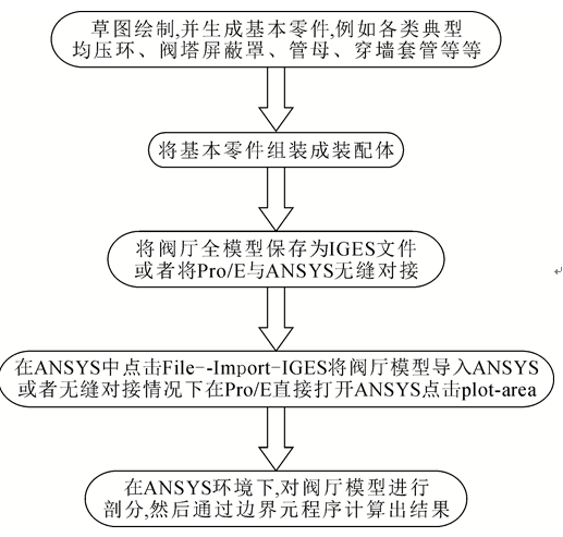 图1
Pro/E及ANSYS计算流程图
Fig.1
Calculation process of Pro/E and ANSYS
图1
Pro/E及ANSYS计算流程图
Fig.1
Calculation process of Pro/E and ANSYS
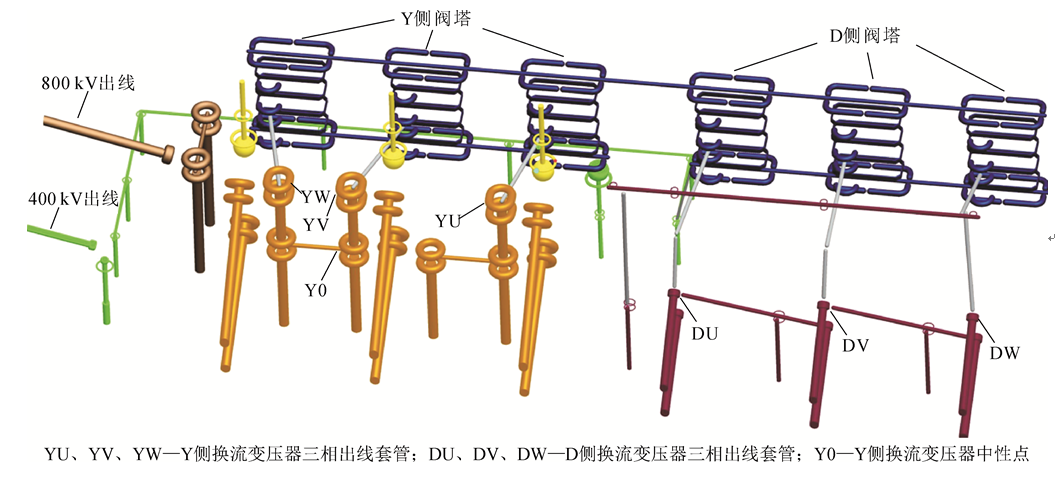 图2
阀厅几何全模型
Fig.2
Full geometry model of valve hall
图2
阀厅几何全模型
Fig.2
Full geometry model of valve hall
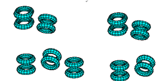 图3
高压端部分金具剖分
Fig.3
Meshing of part of the fittings in the high-voltage terminal
图3
高压端部分金具剖分
Fig.3
Meshing of part of the fittings in the high-voltage terminal
 表1
一个工频周期内的电位分布情况
Table
1 Electric potential distribution conditions within a frequency cycle
表1
一个工频周期内的电位分布情况
Table
1 Electric potential distribution conditions within a frequency cycle
3 阀厅全模型电场计算及结果分析
3.1 阀厅全模型表面电场分布
本文只关注阀厅金具的表面电场,穿墙套管和
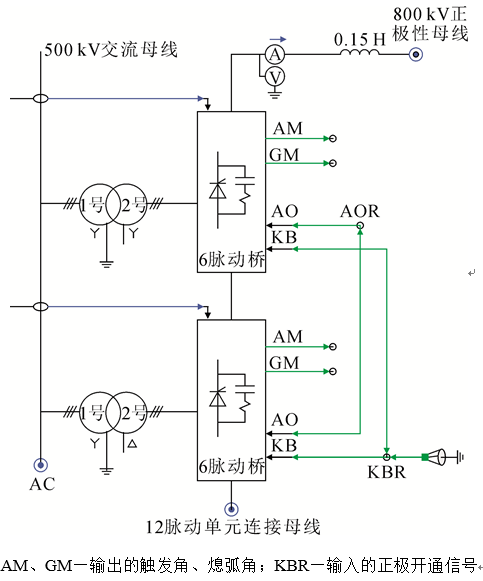 图4
800 kV特高压直流输电系统高压阀厅主接线
Fig.4
Main part of the 800 kV UHVDC system
图4
800 kV特高压直流输电系统高压阀厅主接线
Fig.4
Main part of the 800 kV UHVDC system
支柱绝缘子不作为关注区域,故将其忽略。经对比计算,0.31 s时阀厅金具表面电场出现最大值,限于篇幅,本文仅对该时间阀厅几何全模型表面电场分布云图进行展示。
阀厅全模型表面电场强度分布见
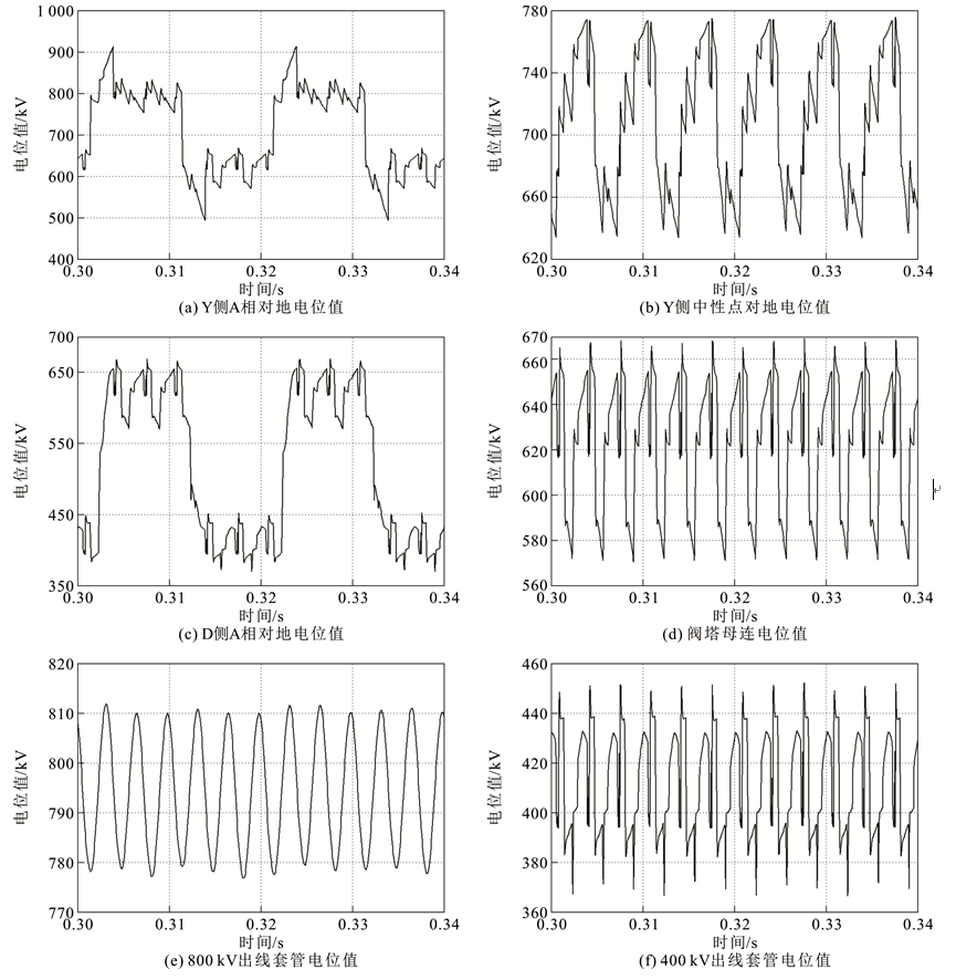 图5
某800 kV特高压直流输电系统各典型金具的电位值
Fig.5
Potential value of a 800 kV UHVDC system’s typical fittings
图5
某800 kV特高压直流输电系统各典型金具的电位值
Fig.5
Potential value of a 800 kV UHVDC system’s typical fittings
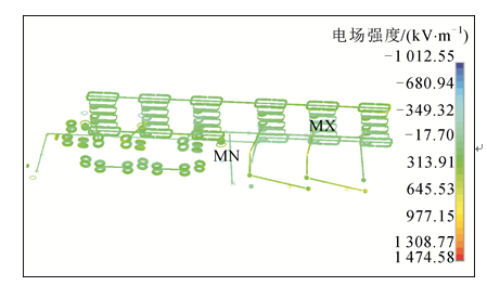 图6
阀厅几何全模型表面电场分布
Fig.6
Surface electric field distribution of full valve hall geometry model
图6
阀厅几何全模型表面电场分布
Fig.6
Surface electric field distribution of full valve hall geometry model
400 kV出线均压环处,为-10.1 kV/cm,其中负号仅代表模型表面的法向方向。
3.2 子模型结果分析
选取阀厅内Y侧B相均压环、D侧避雷器均压环、D侧B相连接铝排处跑道型均压环、400 kV出线连接铝排均压环、800 kV出线均压环以及400 kV出线均压环作为关注区域,其表面电场分布见
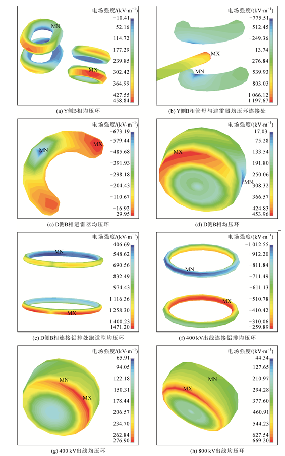 图7
子模型表面电场分布
Fig.7
Surface electric field distribution of sub-model
图7
子模型表面电场分布
Fig.7
Surface electric field distribution of sub-model
角处,原因是模型倒角半径小。其他均压环计算结果合理且表面电场分布过渡平滑,达到了精确求解的目的。
4 结论
1)采用伽辽金边界元法分析阀厅金具电场分布,只需对其表面进行合理剖分,避免了3维模型的复杂剖分处理和后处理中的微分运算,计算代价小且计算精度高。
2)计算结果表明,阀厅金具在当前设计方案下,表面电场强度最大值为14.7 kV/cm,低于起晕场强限值,该计算结果可为阀厅金具的设计提供数据支撑。
参考文献
[1]
[2]
[3]
[4]
[5]
[6]
[7]
[8]
[9]
[10]
[11]
[12]
[13]
[14]
[15]
[16]