Spatial-temporal Evolution of Dielectric Barrier Discharge Filament in Pin-to-plate Geometry at Atmospheric Pressure
李雪辰, 张琦, 楚婧娣, 李霁媛, 贾鹏英
河北大学物理科学与技术学院河北省光电信息材料重点实验室,保定071002
LI Xuechen, ZHANG Qi, CHU Jingdi, LI Jiyuan, JIA Pengying
State Key Laboratory of Photo-electronics Information Materials of Hebei Province, College of Physics Science and Technology, Hebei University, Baoding 071002, China
基金项目:
国家自然科学基金(11575050;
10805013);
河北省自然科学基金(A2015201199;
A2015201092);
Project supported by National Natural Science Foundation of China (11575050, 10805013), Natural Science Foundation of Hebei Province (A2015201199, A2015201092);
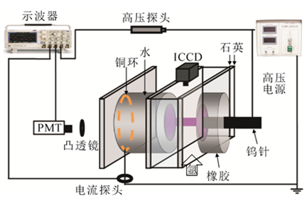
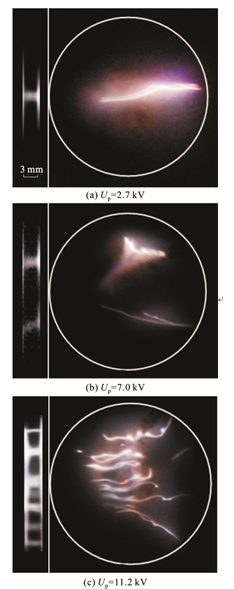
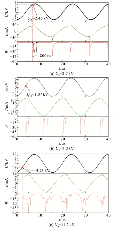
In order to analyze the formation mechanism of the dielectric barrier discharge filament in the small gap, the discharge forming process of streamer discharge mechanism was studied by taking volume discharge and surface discharge as the research object. After using a dielectric barrier discharge device in a pin-to-plate geometry, stable discharge was generated in atmospheric pressure argon. It is found that the discharge transits from a mono-filament into a multi-filament with increasing the peak value of the applied voltage. With increasing the peak voltage, the intensity of the total light emission signal from the discharge increases as well as the light pulse number per half voltage cycle. Moreover, the inception voltage in the positive half cycle increases with increasing the argon flow rate, and decreases with increasing the peak value of applied voltage. Temporal evolution of the mono-filament discharge is investigated during one voltage cycle by an high-speed camera with an exposure time of several nanoseconds. It is found that the discharge consists of volume discharge in the air gap between the two electrodes and surface discharges on the dielectric plates. The volume discharge corresponds to a positive streamer mechanism for both the positive and the negative half voltage-cycles, however, the discharge mechanism of the surface discharge is related with the polarity of the electrode. The surface discharge on the instantaneous cathode corresponds to a positive streamer, and a negative streamer mechanism is involved for the surface discharge on the instantaneous anode.
KEY WORDS :atmospheric pressure discharge;dielectric barrier discharge;filamentary discharge;streamer mechanism;spatial and temporal evolution;
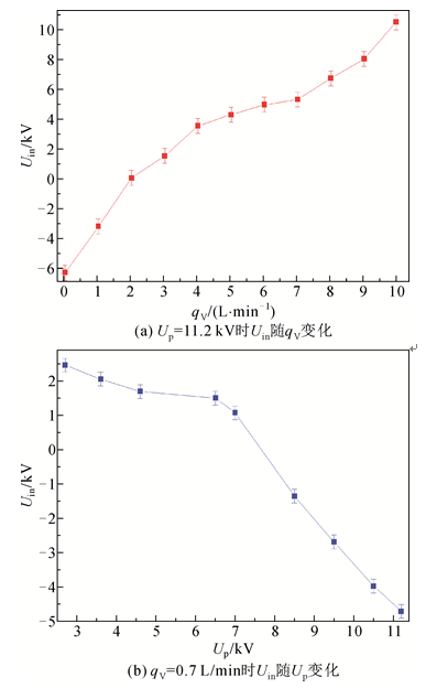
图4
正半周期放电起始电压Uin随氩气体积流量\({{q}_{\text{V}}}\)和外加电压峰值Up的变化关系
Fig.4
Inception voltage in the positive half cycle of the applied voltage as a function of the gas flow rate and the peak value of the applied voltage
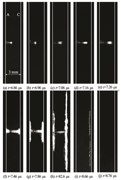
图5
外加电压正半周期单丝放电沿着轴向的时间演化(曝光时间为20 ns)
Fig.5
Temporal evolution of the mono-filament discharge along the axial direction in the positive half cycle of the applied voltage with an exposure time of 20 ns
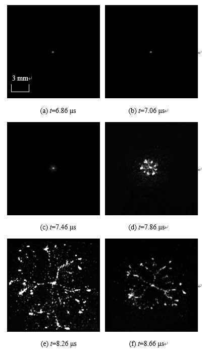
图6
外加电压正半周期单丝放电在瞬时阴极端沿着径向的时间演化(曝光时间为20 ns)
Fig.6
Temporal evolution of the mono-filament discharge along the radial direction of the instantaneous cathode in the positive half voltage cycle (exposure time is 20 ns)
图7
外加电压负半周期单丝放电沿着轴向的时间演化(曝光时间为20 ns)
Fig.7
Temporal evolution of the mono-filament discharge along the axial direction in the negative half voltage cycle with an exposure time of 20 ns
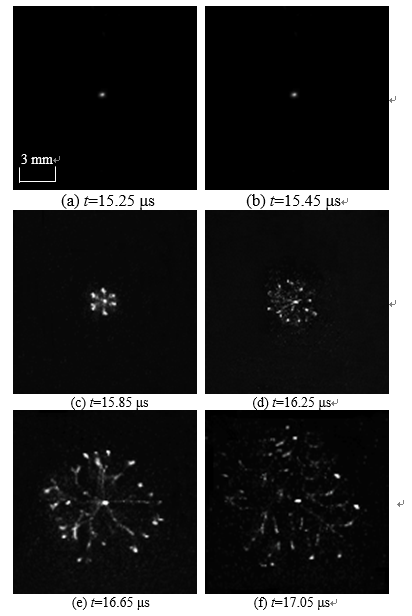
图8
外加电压负半周期单丝放电在瞬时阳极端沿着径向的时间演化(曝光时间为20 ns)
Fig.8
Temporal evolution of the mono-filament discharge along the radial direction of the instantaneous anode in the negative half cycle of the applied voltage (the exposure time is 20 ns)
[2]
KUNZEK, MICLEAM, MUSAG, et al.Diode laser-aided diagnostics of a low-pressure dielectric barrier discharge applied in element-selective detection of molecular species[J]. Spectrochimica Acta Part B Atomic Spectroscopy, 2002, 57(1): 137-146.
[3]
MASSINESF, RABEHIA, DECOMPSP, et al.Experimental and theoretical study of a glow discharge at atmospheric pressure controlled by dielectric barrier[J]. Journal of Applied Physics, 1998, 83(6): 2950-2957.
[4]
CUI NY, BROWNN.Modification of the surface properties of a polypropylene (PP) film using an air dielectric barrier discharge plasma[J]. Applied Surface Science, 2002, 189(Supplement 1/2): 31-38.
[5]
LITTLEU, BUCHANANF, HARKIN-JONESE, et al.Surface modification of poly(epsilon-caprolactone) using a dielectric barrier discharge in atmospheric pressure glow discharge mode[J]. Acta Biomaterialia, 2009, 5(6): 2025-32.
[6]
GEYTER ND, MORENTR, GENGEMBREL, et al.Increasing the hydrophobicity of a PP film using a Helium/CF4 DBD treatment at atmospheric pressure[J]. Plasma Chemistry & Plasma Processing, 2008, 28(2): 289-298.
[7]
BORCIAG, CAZANR, BORCIAC.DBD surface modification of polymers in relation to the spatial distribution of reactive oxygen species[J]. Plasma Chemistry & Plasma Processing, 2011, 31(5): 729-740.
[8]
DORRAKIN, SAFA NN, JAHANFARM, et al.Surface modification of chitosan/PEO nanofibers by air dielectric barrier discharge plasma for acetylcholinesterase immobilization[J]. Applied Surface Science, 2015, 349(15): 940-947.
[9]
SCHMIDT-SZALOWSKIK, RŻANEK-BOROCH Z, SENTEK J, et al. Thin films deposition from hexamethyldisiloxane and hexamethyldisilazane under dielectric-barrier discharge (DBD) conditions[J]. Plasmas & Polymers, 2000, 5(3): 173-190.
[10]
STAROSTIN SA, PREMKUMAR PA, CREATOREM, et al. High current diffuse dielectric barrier discharge in atmospheric pressure air for the deposition of thin silica-like films[J]. Applied Physics Letters, 2010, 96(6): 061502-061502-3.
[11]
王新新,刘凯,罗海云,等. 热刺激电流测量装置及其用于介质阻挡均匀放电的研究[J]. 高电压技术,2015,41(1):245-250.WANGXinxin, LIUKai, LUOHaiyun, et al.Measurement device of thermally stimulated current and its use in uniformity research of dielectric barrier discharge[J]. High Voltage Engineering, 2015, 41(1): 245-250.
[12]
张颖,李凌寒啸,李杰,等. 沿面型介质阻挡放电中高压电极配置对放电特性及臭氧产量的影响[J]. 高电压技术,2015,41(2):539-546.ZHAOYing, LILinghanxiao, LIJie, et al.Influence of high voltage electrode configuration on discharge characteristics and ozone generation in surface dielectric barrier discharge[J]. High Voltage Engineering, 2015, 41(2): 539-546
[13]
PARK GY, PARK SJ, CHOI MY, et al.Atmospheric-pressure plasma sources for biomedical applications[J]. Plasma Sources Science & Technology, 2012, 21(4): 43001-43021.
[14]
KONG MG, KROESENG, MORFILLG, et al.Plasma medicine: an introductory review[J]. New Journal of Physics, 2009, 11(11): 1-35.
[15]
TANGJ, JIANGW, ZHAOW, et al. Development of a diffuse air-argon plasma source using a dielectric-barrier discharge at atmospheric pressure[J]. Applied Physics Letters, 2013, 102(3): 033503-033503-5.
[16]
CHU HY, HUANG BS.Gap-dependent transitions of atmospheric microplasma in open air[J]. Physics of Plasmas, 2011, 18(4): 332-339.
[17]
TANGJ, DUANY, ZHAO W.Characterization and mechanism studies of dielectric barrier discharges generated at atmospheric pressure[J]. Applied Physics Letters, 2010, 96(19): 191503-191503-3.
[18]
AKISHEVY, GRUSHINM, NAPARTOVICHA, et al.Novel AC and DC non-thermal plasma sources for cold surface treatment of polymer films and fabrics at atmospheric pressure[J]. Plasmas & Polymers, 2002, 7(3): 261-289.
[19]
TAY WH, KAUSIK SS, YAP SL, et al.Role of secondary emission on discharge dynamics in an atmospheric pressure dielectric barrier discharge[J]. Physics of Plasmas, 2014, 21(4): 241-271.
[20]
QIB, HUANGJ, QIUY, et al. Diagnosis of the ion density in two discharge modes generated in atmospheric pressure argon with pin-to-plate dielectric barrier geometry[J]. Physics of Plasmas, 2011, 18(8): 083302-083302-6.
[21]
AKISHEVY, APONING, BALAKIREVA, et al.DBD surface streamer expansion described using nonlinear diffusion of the electric potential over the barrier[J]. Journal of Physics D: Applied Physics, 2013, 46(46): 771-780.
[22]
SUNL, HUANGX, ZHANGJ, et al.Discharge dynamics of pin-to-plate dielectric barrier discharge at atmospheric pressure[J]. Physics of Plasmas, 2010, 17(11): 1498-1506.
[23]
俞哲,张芝涛,于清旋,等. 针-板DBD微流注与微辉光交替生成的机理研究[J]. 物理学报,2012,61(19):308-316.YUZhe, ZHANGZhitaoyu, YUQingxuan, et al.Atmospheric pressure streamer and glow-discharge generated alternately by pin-to-plane dielectric barrier discharge in air[J]. Acta Physica Sinica,2012, 61(19): 308-316.
[24]
CHU HY, LIOU BT.Gap-dependent arrangements of dielectric barrier discharges in open air[J]. Physics of Plasmas, 2014, 21(8): 1181.
[25]
LI XC, WANGL.Discharge characteristics in atmospheric pressure glow surface discharge in helium gas[J]. Chinese Physics Letters, 2005, 22(2): 416-419.
[26]
WANGZ, REN CS, NIE QY, et al.Effects of airflows on dielectric barrier discharge in air at atmospheric pressure[J]. Plasma Science & Technology, 2009, 11(2): 177-180.
[27]
张芝涛,张志鹏,俞哲. 大气压介质阻挡微放电通道的相互作用[J]. 高电压技术,2015,41(9):2880-2887.ZHAOZhitao, ZHAOZhipeng, YUZhe.Interaction between micro discharge channels in dielectric barrier discharge at atmospheric pressure[J]. High Voltage Engineering, 2015, 41(9): 2880-2887.
[28]
TIMATKOV VV, PIETSCH GJ, SAVELIEV AB, et al.Influence of solid dielectric on the impulse discharge behaviour in a needle-to-plane air gap[J]. Journal of Physics D: Applied Physics, 2005, 38(6): 877-886.